
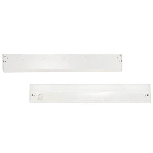

LED Under Cabinet Light
Features
• Metal body give fine quality look and feel,
• High diffusion PC lens give uniform light output
• Direct 120VAC input, save all the trouble with adapters
• Linkable design with accessories included
• Two knock-outs design give you the best flexibility
• on installation.(one at the back,one at the top)
• Traditional switch give you enough confidence for operating
• Dimmable with most of the popular dimmers
• Reliable & Long Lifespan
LED Under Cabinet Light

Features
• Metal body give fine quality look and feel,
• High diffusion PC lens give uniform light output
• Direct 120VAC input, save all the trouble with adapters
• Linkable design with accessories included
• Two knock-outs design give you the best flexibility
• on installation.(one at the back,one at the top)
• Traditional switch give you enough confidence for operating
• Dimmable with most of the popular dimmers
• Reliable & Long Lifespan

Application
• Kitchen / Counter / Shelf / Workbench / Showcase
Dimmensions

Installation
1、Supply wires connection via rear access door: The rear access door that is located in the middle of the back of housing has its own
knockout for quick connection to supply wires, foregoing the need to remove the lens cover and open the wiring compartment.
See Figure 1

2 、Remove knockout by using a hammer or punch; then loosen screw that secures rear access door using a screwdriver or driver
bit. See Figure 2
3、Install 3/8 cable connector (included) for the supply wire following National Electric Code and local codes through this knockout on access door. See Figure 3. Use 14 or 12AWG wires. AC should be protected by circuit breaker or fuse.

4 、Strip back jacket on supply wires to 3/8 and use push-in wire connectors inside housing to connect wires (Black to Black/Hot,
White to White/Neutral and Yellow/Green stripe <Ground> to bare wire) through knockout so that push-in connectors are positioned on the housing side of the access door. See Figure 4.
5、Replace rear access door and secure with screw.
Note:Be sure that the wires are not pinched or damaged by any part of the housing or the cover. See Figure 5.

6、Determine locations for each fixture. Make sure the distance between fixtures to be interconnected does not exceed 12”
7、Use screwdriver or driver bit to tighten captive mounting screws and secure fixture to an appropriate mounting surface.


Contact: Yang Yang
Phone: 13586052222
E-mail: info@ullusa.com
Add: 120 Clyde Road, Somerset, NJ 08873